Contents
Index
Config File
The GeoCadastre config file can be used to set general program attributes and also to
extend the data fields in various dialog boxes.
It is written in XML and is usually located in the same folder as the GeoCadastre.exe program file.
You can edit the file with a text editor like Notepad.
You can change values in the file to affect verious aspects of GeoCadastre display and behaviour.
The default file is called "GeoCadastre_config.xml"
Important: You tell GeoCadastre which config file to use in the File/Program Settings menu option.
Structure of the file
- State Jurisdiction
- Display and Other Options
- Define Extra Parcel Attributes
- Define Extra Plan Attributes
- Define Extra Line Attributes
- Define Extra Control Attributes
- GIS Tools Menu
- Define Valid Locality Types
- Define Valid Parcel Types
- Define Valid Line Types
State Jurisdiction
You can set the state so that when state based rules are applied GeoCadastre will apply approriate rules.
A typical entry is like this.
<state>NSW<state>
Valied entries are 'NSW', 'VIC, 'ACT', 'QLD', 'SA', 'WA', 'NT', 'TAS'
Display and Other Options
Parcels Display
The values shown here are the default values.
<selectedParcelLines thickness="0.8" />
Setsthe thickness of the Selected line when Editing a parcel
Points Display
The values shown here are the default values.
<pointsDisplay symbol="1" symbolSize="2" symbolColour="Red" textSize="2.0" textAngle="90" textColour="Teal" />
- symbol="1" - sets the displayed symbol to symbol 1. More Symbols Info.
- symbolSize="2" - sets the display symbol size to 2mm
- symbolColour="Red" - sets the symbol colour to Red. More Colours.
- textSize="2.0" - sets the point number text to 2mm
- textAngle="90" - sets the point number text angle to 90deg (survey brg) - horizontal to the right
- textColour="Teal" - defines the point number text colour. More Colours.
Control Point Display
The values shown here are the default values.
<controlPointsDisplay symbol="7" symbolSize="3" textSize="3.0" textAngle="120" />
- symbol="7" - sets the displayed symbol to symbol 7. More Symbols Info.
- symbolSize="3" - sets the display symbol size to 3mm
- Note: The symbol/text colour is not settable as the program uses Blue for inactive control points and Red of Active control points
- textSize="3.0" - sets the control point name text to 3mm
- textAngle="120" - sets the point number text angle to 120 deg (survey brg)
A tip: If you want the old control point symbol - leave out the 'symbol="7"' entry.
Parcel Dialog Prompts
These options allow you to change the prompt text on the Parcel dialog box.
<parcelUserIdText> Locality </parcelUserIdText>
<parcelTagText> Type </parcelTagText>
Joining Residuals Decimals
This option allows you to change the number of decimal places displayed for the residuals when joining.
<joinResidualsDecimals> 2 </joinResidualsDecimals>
The default value is 2 decimal places which will be used if this parameter is absent.
Automatic Line Point Connections
This allows Auto-Join to create line points on 999 connections.
<autoLinePtsConnections> 2 </autoLinePtsConnections>
The default value is No if this parameter is absent.
Enter a 'Yes' to enable this action.
Copy Check Parcel Result to Parcel Description
This option allows you to copy the Check Parcel (misclose) result to the parcel description.
<autoCopyCheckparcel> 2 </autoCopyCheckparcel>
The default value is No if this parameter is absent.
Enter a 'Yes' to enable this action.
Erase Unjoin Points
When a parcel is unjoined, the points are left in place for later use.
You can have them automatically deleted by the unjoining action by setting the option in the config file.
<eraseUnjoinPoints> Yes </eraseUnjoinPoints>
The default is No if this parameter is absent.
Enter a 'Yes' to enable this action.
Management of Points
When a parcel is joined, points are created for the parcel corners that are not connected to the parcel
network during the joining process.
When a parcel is unjoined, the unjoining process can also delete any point that is no longer
connected in the parcel network. While this is useful in cleaning up the data, there are times when
this is not desirable.
For example, if the data set has come from a GIS or data base, the database "pointID" will be
stored with the point so that the correct point can be updated when the data set is returned.
This sets up the way that isolated points are treated when a parcel is unjoined.
If it is set to "YES", the points that are not connected to the network will be deleted
and any control point that is attached to them will also be deleted.
If the parcel is then joined back on to the network, new points will be created for the "non-connected" points.
If it is set to "NO", the points that are no longer connected to the network will be retained
and a linkage will be created between each point and the corresponding point on the unjoined parcel.
If a control point is attached to one of these points, it will also be retained and linked to the parcel.
Any "unconnected" control points will be coloured yellow
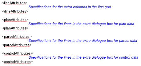
Define Extra Plan Attributes
You can define additional attribute to be entered for a Plan.
Press the "Extra" button on the Plan dialog and you can then enter or edit these additional attributes.
Each entry in the config file will add an extra line to the Extra dialog box.
See the example in the starndard config file GeoCadastreConfig.xml
Define Extra Parcel Attributes
You can define additional attribute to be entered for a Parcel.
Press the "Extra" button on the Parcel dialog and you can then enter or edit these additional attributes.
Each entry in the config file will add an extra line to the Extra dialog box.
See the example in the standard config file GeoCadastreConfig.xml
Define Extra Line Attributes
You can define additional attribute to be entered for a Line.
Each entry in the config file will add an extra column to the data entry grid for lines.
See the example in the standard config file GeoCadastreConfig.xml
Define Extra Control Point Attributes
You can define additional attribute to be entered for a Control Point.
Press the "Extra" button on the Parcel dialog and you can then enter or edit these additional attributes.
Each entry in the config file will add an extra line to the Extra dialog box.
See the example in the standard config file GeoCadastreConfig.xml
Extra Data Attributes
Each area is defined by an attributes statement and the general layout is as follows:
Each attribute has a number, a heading, an extended attribute field and an edit type as shown below.
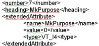
This defines the line number for Plan, Parcel and Control point data in the new dialog box.
It defines the column number for extensions to the parcel line grid.
<heading>
This has the text for the heading of the line or column
<extendedAttribute>
Each extended attribute has a name, a value and a type field and these specify how the extra data will be
held in the job.
<name>
The name identifies the attribute
<value>
The value field can have one of two options:
<value>0</value> The data will be stored as an "extendedAttribute"
<value>struct_data</value> The data is an existing element in the data system
If the value is "struct_data" then the name must be the same as the name in the name of the correct
element in the core database system.
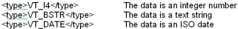
<type>
The type field can have one of three options:
<editType>
Specifies the type of field in the dialog box for the data.
There are two types of fields as follows:
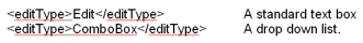
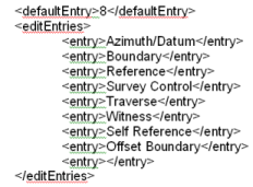
Combo boxes require a list of "prompts" and these are each specified as an "entry" in an "editEntries"
section after the "editType" specification.
The "defaultEntry" defines the entry that will appear when the dialog is first opened if no
existing data has been loaded.
The first entry is number 0 so default entry 8 refers to the ninth line.
GIS Tools Menu
Define Valid Locality Types
You can define any number of valid locality types (UserId).
These values will be used in the 'Plan Examination' report to check that only correct values are used.
<localityTypes>
<locality code="200" descr="DARWIN" />
.....
<locality code="890" descr="YULARA"/>
</localityTypes>
Define Valid Parcel Types
You can define any number of valid Parcel types.
These values will be used in the 'Plan Examination' report to check that only correct values are used.
<parcelTypes>
<parcelType type="" descr="Lot"/>
<parcelType type="0" descr="Lot"/>
...
<parcelType type="21" descr="Road Parcel"/>
Define Valid Line Types
You can define any number of valid Line Types.
These values will be used in the 'Plan Examination' report to check that only correct values are used.
<lineTypes>
<lineType type="000" descr="" colour="Black" style="0" thickness="0.3" />
....
<lineType type="021" descr="Road" Colour="Gold" style="0" thickness="0.6"/>
Colours
You can enter colour names or values, Click
here for more info.